Ievadiet dažus vārdus, lai atrastu saturu.
piemēram: drošinātājs, aizturētājs, 00110115 technical, MCCB...
Jaunākās meklēšanas
Tehniskais atbalsts
This email address is being protected from spambots. You need JavaScript enabled to view it.
Selected Requirements for the Design and Development of Enclosures for Low-Voltage Switchgear by ETI

Selected Requirements for the Design and Development of Enclosures for Low-Voltage Switchgear by ETI

Selected Requirements for the Design and Development of Enclosures for Low-Voltage Switchgear by ETI

When designing low-voltage switchgear, many manufacturers follow guidelines from standards to create and market a product that meets all necessary requirements and ensures safety.

Why Are gPV Fuses the Safer Choice for Solar Power

Why Are gPV Fuses the Safer Choice for Solar Power

Why Are gPV Fuses the Safer Choice for Solar Power

When it comes to solar energy systems, selecting the right components is not just a matter of efficiency—it’s a critical safety decision. Among the most essential components are electrical fuses, which protect systems from overcurrents and faults. Specifically, the debate between gPV fuses, designed for photovoltaic (PV) systems, and gG fuses, used in general electrical applications, often arises. While gPV fuses are more expensive, their design specifically addresses the unique challenges of solar energy systems, making them the safer choice.

Selectivity of protection in electrical installations: Nh fuse-link vs. Miniature circuit breaker

Selectivity of protection in electrical installations: Nh fuse-link vs. Miniature circuit breaker

SELECTIVITY OF PROTECTION IN ELECTRICAL INSTALLATIONS: NH FUSE-LINK VS. MINIATURE CIRCUIT BREAKER

The selectivity of protective devices is a crucial consideration when designing low-voltage installations. The goal of selectivity is to minimize the consequences of a fault. Only the faulty part of the installation should be disconnected, while the rest remains operational. Selectivity is achieved if the fault is cleared by the protective device closest to the fault without triggering other protective devices.


TT Distribution System Regarding Grounding and Fault Protection

TT Distribution System Regarding Grounding and Fault Protection

TT Distribution System Regarding Grounding and Fault Protection

An important element in protecting humans (as well as property and animals) from the effects of electric current is the grounding of the system—this involves the grounding of the point of the electrical supply system and the grounding of exposed conductive parts.


Improving DC EV Charger Maintenance with IR-Based C IR Indication

Improving DC EV Charger Maintenance with IR-Based C IR Indication

Improving DC EV Charger Maintenance with IR-Based C IR Indication


As electric vehicles (EVs) continue to gain popularity, the demand for fast and reliable charging infrastructure is surging. This has led to an increasing focus on ensuring that EV chargers, particularly DC fast chargers, operate efficiently and remain accessible to drivers during long journeys. One of the critical challenges in maintaining these charging stations is minimizing downtime caused by electrical failures, which can disrupt service and delay repairs. In this case study, we explore how ETI’s innovative C IR indication module provides a cutting-edge solution for monitoring and maintaining the electrical wiring within DC EV chargers, improving both reliability and maintenance efficiency.


1. Fast DC Chargers


Electric vehicles (EVs) are becoming more common, and with them, there is an increasing demand for reliable and accessible charging infrastructure.

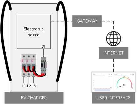
The main purpose of DC EV chargers is to quickly refill the EV battery during long journeys. Consequently, EV chargers are usually positioned along highways at existing petrol stations. The distance between EV charging stations can be considerable, and any failure in the electrical wiring results in an unexpected and unwanted shutdown of the charging station. Because of the long distances between stations, maintenance is more difficult, as it takes time for the maintenance team to reach the failed device. Any information regarding the potential failure is highly valued.

TN Earthing System Regarding Grounding and Fault Protection

TN Earthing System Regarding Grounding and Fault Protection

TN Earthing System Regarding Grounding and Fault Protection

An important element in protecting people (including property and animals) from the effects of electric current is grounding the part – the point of the electrical power supply system (e.g., a 20/0.4 kV transformer station from which a building is powered) and grounding exposed conductive parts. The exposed conductive part (such as the stove housing) is normally not under voltage, but if the phase conductor comes into contact with the housing due to a fault, it can be dangerous if touched. 


Project PODIFER - EFI-P4 eV

Project PODIFER - EFI-P4 eV

Project PODIFER - EFI-P4 eV


In the ever-evolving landscape of electrical installations, staying at the forefront of innovation is paramount. Enter Project PODIFER – a venture aimed at developing specialized RCDs for the next generation of electrical installations, aligning seamlessly with the 'European Green Transition.' These installations are envisioned to incorporate various charging stations for electric vehicles and energy storage systems.


Matija Strehar

Head of R&D Switches

Difference between AC and A type RCDs

Difference between AC and A type RCDs

Difference between AC and A type RCDs


RCD is an international term and stands for Residual Current Device, which serves as a crucial safety device intended to safeguard individuals from potential fatal electric shocks when they come into contact with live elements like exposed wires. Additionally, it can offer a degree of protection against electrical fires, providing a level of personal safety that surpasses what conventional fuses and circuit-breakers can offer. There are two versions of protective current switches: RCCB, residual current circuit breaker and RCBO, residual current circuit breaker with overcurrent protection. In this blog, we will talk about the RCCB version, i.e. the one without overcurrent protection.


As the RCDs offer a high degree of protection against electric shock, these devices are indispensable in residential and commercial premises, and very often they are mandatory, for example in bathrooms, fire-hazardous buildings... Let us take a look at different types of RCCBs and explain the difference between type AC and type A, as well as also touch on type B, which will increasingly be used in the future.


Operation of RCD - AC type example

All users of electrical devices know that careless and incorrect handling of electrical installations and devices can be the cause of fire and other damage, personal injury and even fatality. The use of an RCD significantly reduces the number of fatal accidents due to electric shock, and also reduces the number of fires, caused by poor insulation of electrical cables. Thus, the RCD, in addition to the possibility of switch manipulation (switching on or off), is used for protection in the event of a malfunction, as additional protection and also protection against fire.

In the following, we will try to explain the operation of the RCD on the example of an AC type RCD, and then we will also summarize type A and type B.
 

In Figure 1 we see a two-pole RCD of the AC type. How do we know it's type AC?


Figure 1: Two-pole RCD (EFI 2P) (63 A / IDn=100 mA)


That it is type AC can be seen by the mark on the top right in the rectangle, which is also shown in Figure 2.


Figure 2: indication on the RCD that it is an AC type


The next two important data on the RCD are the rated current (in Figure 1 it is 63 A), and the values are standardized for currents from 10 to 125 A. This is the current that the main contacts can withstand. The next important piece of information is the rated residual current (IDn). In practice, RCDs with the following rated residual currents are mostly used: 10mA, 30mA, 100mA, 300mA and 500 mA (0.5 A).

If we look at Figure 3 and imagine that we have the AC type RCD from Figure 1, let's try to explain the operation of the switch. Let's imagine that the resistance R is initially very high and we start reducing it. The current measured by the A-meter increases from a value of 10mA, 20mA..., but when it reaches somewhere between 50mA and 100mA, the switch turns off. We see that the current flows along the phase conductor (L) past the RCD and then along the neutral conductor (N) through the RCD. If the current flowed through the phase conductor through the RCD and back through the neutral, there would be no tripping.


Figure 3: Explanation of the operation of the RCD


Figure 4: four-pole RCD in the TT power supply system (principle of operation - fault current flow)


Since the RCD serves as protection against electric shock by automatically disconnecting the power supply in electrical installations, let's try to explain it even better. The RCD is always activated at a current that occurs in the event of a certain fault. Thus, in the TT power supply system (Figure 4), in the event of a fault in an individual device or consumer (for example, a live conductor comes into contact with the housing of the stove, which could be very dangerous for the user). The fault current flows through the stove housing through the protective conductor (PE conductor), further through the protective grounding (Ra), which is at the building, then through the ground to the operational grounding (Ro) of the transformer station, then through the low-voltage winding of the transformer and through the phase conductor (via the low-voltage network and the low-voltage installation itself) to the consumer. This represents the electrical circuit of our fault current. All metal casings of electrical devices are grounded with a protective conductor, where the insulation is yellow-green in color. In the RCD, an asymmetry of the electric current occurs, since the sum of the incoming currents is not the same as the outgoing currents, and the RCD switch turns off in less than 30 ms, which is very important for people's safety. The difference in currents is known as residual current. If the residual current exceeds the value required to trip the tripping mechanism of the RCD, the RCD will trip the circuit. Figure 4 shows a four-pole RCD (40 A/0.3), or with a residual current (IDn) of 0.3 A. In this case, the RCD switch will trip between 0.15 A and 0.3 A. Since the fault current is significantly greater, the shutdown is immediate.

Now let's return to RCD types. The AC type is sensitive to alternating residual current, i.e. where fault currents are expected to be sinusoidal (Figure 2). The AC type RCD actually trips between 50 and 100% of the rated residual current, as manufacturers use standardised permissible limits. 

AC switches with a residual current of 0.3 A are very often used for installations in buildings for regular use (Figure 4). If it says 40 /0.3A on the RCD, that means 40 A is the electrical current that the main contacts of the can withstand, and 0.3 A is the nominal residual current. The fuse or MCB in front of the RCD must be less than 40 A, to protect the contacts of the RCD itself.
 
Therefore, the RCD does not trip when the sum of the inflow currents through the phase conductors is equal to the outflow current through the neutral conductor. It only trips when the fault current flows along the protective conductor past the RCD, and the resulting current asymmetry creates a condition for the switch to turn off.
 
From the explained example, it is clear that the RCD does not interrupt in case of overload and short circuits between the phase conductors or between the phase and neutral conductors, which many people mistakenly think. Figure 5 shows a single-pole short-circuit where the installation circuit breaker or fuse trips, but not the RCD, since there is no asymmetry of the currents in the RCD. It switches off in the event of a faulty current, which can also be called an earth short circuit.


Figure 5: An example of a single-pole short circuit where the miniature circuit breaker trips


RCD type A
Figure 6 shows a type A RCD, identified by the symbol in the upper right rectangle, which is also shown by the symbol in Figure 7.


Figure 6: Type A RCD (16A/300mA)


Figure 7: Symbol of type A, RCD


What is the difference between type A and type AC?

A type, in addition to alternating current, is also sensitive to half-wave or full-wave directional alternating current (pulsating direct current). An example are rooms with an increased risk, such as the bathroom, where an RCD with a rated differential current of 0.03 A (30 mA) is mandatory, as consumers such as fans are used there, which have half-wave rectification with a diode for a certain function. A type of RCD trips between 35 and 140% of the rated residual current. So for an RCD with a residual current of 30 mA it trips between 10.5 mA and 42 mA. Manufacturers use standardised tolerances.

Figure 8 shows a type B RCD, which is even rarer in electrical installations. Due to the extraordinary increase in various electronic devices with rectifiers, an increase in the use of this type of RCD can be expected.


Figure 8: four-pole RCD type B (16A/30mA)


The B type RCD can be recognized by the symbols in those three rectangles above in Figure 8. The B type, in addition to alternating and pulsating direct current, also works with smooth direct residual current and also with high-frequency currents. It is used in facilities where we have e.g. three-phase rectifiers, frequency converters and other electronic devices. The B type of RCD, on the other hand, trips between 50 and 200% of the nominal residual current.


You can find more details regarding the RCDs in our manual.

And here is a cheatsheet  on various types of RCDs and applications they are used in.


Fuse Selection with ETIFUSE

Fuse Selection with ETIFUSE

Revolutionizing Fuse Selection with ETIFUSE - An Online Comparative Tool

ETIFUSE is an award winning innovative online tool that will speed up and eliminate the guess work from the fuse selection process. It simplifies and streamlines the process of analysing I/t characteristics of fuse-links, offers interactive, accurate comparisons, adheres to international standards, and provides a user-friendly interface for efficient fuse selection. A must-try for those seeking to enhance safety and efficiency in electrical design.


Sabina Pešec, M.Sc.
ETIFUSE project manager

 
Patented ETIMAT P construction for a longer service life

Patented ETIMAT P construction for a longer service life

Patented ETIMAT P construction for a longer service life

The new construction of ETIMAT P miniature circuit breakers, protected by two European patents, ensures a superior electrical endurance and highest electric strength. Unique on the market, a combined thermo-magnetic tripping unit enables precise and reliable shutdown and prevents manual tampering of the overload settings. ETIMAT P are versatile, strong and durable and designed to rationalize mounting and usage.


Domen Janc
R&D


As the advantages of the new generation of ETIMAT P, we can point out reduced power dissipation, longer lifetime of the product, less impact on the environment during the production of the devices, as well as their automated assembly of the product ensures precise traceability and the highest quality control. Each product has a QR code with a link to the product website with all the relevant information, operating instructions and other technical materials. The miniature circuit breaker can be connected to the busbar and conductor at the same time, both from above and below, using wires with a connecting crossection up to 25mm2.

 
Construction of new generation ETIMAT P

With the new construction, we reduced the number of technological processes, especially the number of necessary welds, which we succeeded in with the new patented assembly of the movable contact. This new construction also enables complete automation of product assembly.

We also wanted to improve the functionality of the new generation of devices in tests of the short circuit capacity, which we succeeded in by constructing new parts of the mechanism. The new mechanism provides adequate tripping dynamics, contact opening speed and has one of the largest final inter-contact distances, which means improved dielectric breakdown strength. It also enables easy connection of single-pole devices into multi-pole versions and quick and easy installation of existing ETI accessories (auxiliary switches, remote switch-off switch, etc.) by end users and, of course, their reliable operation.

 
The assembly of the movable contact - a patented solution

The most original design solution in ETIMAT P is represented by the composition of the movable contact with, which enables:

- adequate contact force

- corresponding decreasing torque on the movable contact when the mechanism is switched off (dynamics when opening)

- a very large inter-contact distance (improved dielectric breakdown strength in the off state) and

- provides a superior number of cycles in lifetime tests (on/off).


The assembly ensures adequate mobility of the flexible contact and electrical conductive properties without the need to use flexible copper braids or to weld individual parts.


Assembly of the movable contact ETIMAT P


Combined tripping unit – a patented solution

The heart of ETIMAT P is the so-called combined tripping unit, which combines the function of thermal tripping, conditioned by the occurrence of a long-term current overload, and instantaneous electromagnetic tripping, conditioned by the occurrence of a short-circuit current. Other miniature circuit breakers on the market have thermal tripping units separate from the electromagnetic one, but in ETI's solution, both are combined into one assembly.


Electromagnetic tripping unit with a magnetic coil

The magnetic coil is different for each characteristic. As a consequence, the MCB doesn’t need any additional adjustments, and there is no possibility of manual tampering.

Integrated thermal release with bimetallic disc

This part of our patented innovation works as a substitute for the long bimetallic strip used in other MCBs. This solution prevents degradation of the bimetallic strip due to permanent electrical loading of the material. This ensures a stable, unchanged tripping characteristic of each ETIMAT P during its entire lifetime.

Operation of the combined tripping unit

In the event of an electrical overload, the increased electric current in the wire of the coil wound on the combination tripping unit generates heat, which heats the aluminum cylindrical crucible of the tripping unit. The resulting heat is transferred through the crucible to the thermobimetallic disc inside the tripping unit, which when heated reaches a specific temperature and fires the striker pin. At an even higher electric current, typical of a short circuit, the tripping unit fires instantly like an electromagnet due to the generated increased magnetic field. Then the striker pin is pushed by the movement of the magnetized iron arm against the fixed iron core, which is fixed in a pot inside the tripping unit. In both cases, the striker pin releases the mechanism and consequently causes the electrical shutdown of the device.


New, optimized arc chamber

All manufacturers of miniature circuit breakers install an arc chamber in their products, the role of which is to cool and extinguish the electric arc ("electric lightning") that occurs when the device is switched off at a high short-circuit current. It consists of iron tiles called lamellas and a supporting frame for fixing them, made of a special heat-resistant non-combustible cardboard (called "vulkan fiber").

For the ETIMAT P, we have developed a new optimized arc chamber, which has a more durable and slightly thicker casing with special round exhaust holes on the back. Round holes are an innovative solution that ensure adequate air permeability at increased pressure in short circuit conditions and at the same time successfully stop the traveling larger hot ionizing particles created under the influence of an electric arc when melting parts of conductive metal surfaces.


Arc chamber ETIMAT P


All major components are marked with a DMC code containing the individual test results, ensuring exact traceability and the highest quality control of each MCB.


Jūsu grozs ir tukšs.